Arduino Board Overview and Pinout
Arduino Board Overview and Pinout
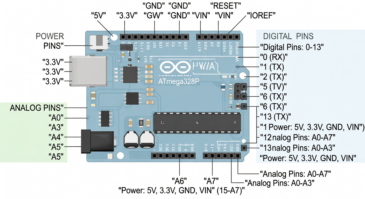
Arduino Uno Layout
The Arduino Uno is the most popular board. Let's understand its components:
Main Parts
| Part | Description |
|---|---|
| USB Port | Power and programming connection |
| Barrel Jack | External power input (7-12V) |
| Reset Button | Restarts the sketch |
| ATmega328P | Main microcontroller chip |
| LED Sockets | Built-in LED on pin 13 |
| Power Pins | 5V, 3.3V, GND |
| Analog Pins | A0-A5 for sensors |
| Digital Pins | D0-D13 for inputs/outputs |
Understanding the Pins
Digital Pins (0-13)
Digital pins can read or write two states: HIGH (5V) or LOW (0V).
- PWM Pins: Pins 3, 5, 6, 9, 10, 11 support PWM (Pulse Width Modulation)
- Serial Pins: Pin 0 (RX) and 1 (TX) for serial communication
- SPI Pins: Pin 11 (MOSI), 12 (MISO), 13 (SCK)
Analog Pins (A0-A5)
Analog pins read voltages from 0 to 5V with 10-bit resolution (0-1023 values).
Power Pins
| Pin | Voltage | Use |
|---|---|---|
| 5V | 5V | Power sensors and modules |
| 3.3V | 3.3V | Low-power sensors |
| GND | 0V | Ground reference |
| Vin | 7-12V | External power input |
Pin Mapping
digitalWrite(pin, HIGH)  -> Sets pin to 5V
digitalWrite(pin, LOW)   -> Sets pin to 0V
analogRead(pin)          -> Reads 0-1023 (0-5V)
analogWrite(pin, value)  -> PWM output 0-255
Built-in LED
Arduino Uno has a built-in LED connected to pin 13. This is useful for testing without external components.
Onboard Components
- Power LED: Lights when board has power
- TX/RX LEDs: Flash during serial communication
- LED on Pin 13: Programmable LED
Shields and Accessories
Shields are circuit boards that stack on top of Arduino:
| Shield | Function |
|---|---|
| Ethernet Shield | Network connectivity |
| WiFi Shield | Wireless connectivity |
| Motor Shield | Control DC motors |
| LCD Shield | Display text |
| Relay Shield | Control high voltage |
Connecting Arduino
Via USB
Connect Arduino to your computer using a USB cable (Type-B for Uno, micro-USB for Nano).
Power Options
1. USB: 5V from computer 2. Barrel Jack: 7-12V adapter 3. Vin Pin: 7-12V from circuit
Warning: Never exceed 12V on the barrel jack or Vin pin!
Summary
Understanding the Arduino pinout is essential:
- Digital pins for on/off signals and PWM
- Analog pins for reading variable voltages
- Power pins to supply external components
- PWM pins for variable output (motors, LEDs)
Next Lesson
In the next lesson, you'll learn how to install the Arduino IDE on Windows.
Quiz - Quiz - Arduino Board Overview
1. How many digital I/O pins does Arduino Uno have?
2. Which pin has a built-in LED on Arduino Uno?
3. What voltage do the 5V and 3.3V pins provide?
4. Which function configures a pin as input or output?