Digital Inputs and Outputs
Digital Inputs and Outputs
Understanding Digital I/O
Digital I/O (Input/Output) is the foundation of Arduino. Digital signals have only two states: ON or OFF (HIGH or LOW).
Input vs Output
| Type | Description | Example |
|---|---|---|
| INPUT | Reads state from device | Push button, switch |
| OUTPUT | Controls other devices | LED, motor, relay |
Digital Output
We've already seen digital output with LEDs. Now let's expand:
Multiple LEDs
Connect and control multiple LEDs:
int led1 = 10;
int led2 = 11;
int led3 = 12;void setup() {
pinMode(led1, OUTPUT);
pinMode(led2, OUTPUT);
pinMode(led3, OUTPUT);
}
void loop() {
digitalWrite(led1, HIGH);
digitalWrite(led2, LOW);
digitalWrite(led3, LOW);
delay(500);
digitalWrite(led1, LOW);
digitalWrite(led2, HIGH);
digitalWrite(led3, LOW);
delay(500);
digitalWrite(led1, LOW);
digitalWrite(led2, LOW);
digitalWrite(led3, HIGH);
delay(500);
}
Digital Input
Reading buttons and switches:
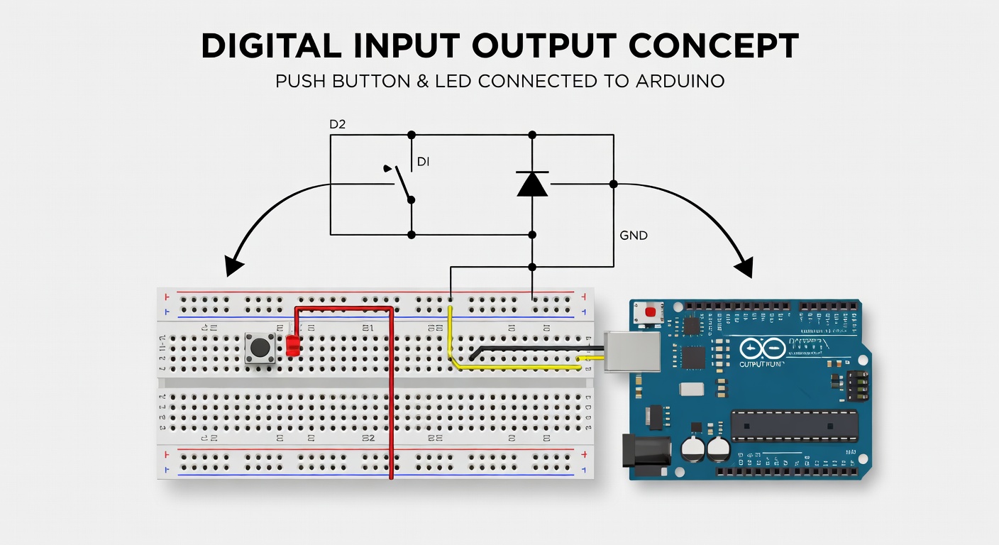
Connecting a Button
Connect a push button:
1. One leg to Arduino pin 2 2. Other leg to GND through 10kΩ resistor (pull-down) 3. Connect 5V to button through internal pull-up
Button Circuit
5V ---[Button]--- Pin 2 ---[10kΩ]--- GND
Reading Button State
int buttonPin = 2;
int ledPin = 13;void setup() {
pinMode(buttonPin, INPUT);
pinMode(ledPin, OUTPUT);
}
void loop() {
int buttonState = digitalRead(buttonPin);
if (buttonState == HIGH) {
digitalWrite(ledPin, HIGH); // LED on
} else {
digitalWrite(ledPin, LOW); // LED off
}
}
Using Internal Pull-Up
Arduino has built-in pull-up resistors:
void setup() {
  pinMode(2, INPUT_PULLUP);  // Enable internal pull-up
}
With INPUT_PULLUP:
- Button pressed = LOW
- Button released = HIGH
Complete Example with Pull-Up
int buttonPin = 2;
int ledPin = 13;void setup() {
pinMode(buttonPin, INPUT_PULLUP);
pinMode(ledPin, OUTPUT);
}
void loop() {
if (digitalRead(buttonPin) == LOW) {
digitalWrite(ledPin, HIGH);
} else {
digitalWrite(ledPin, LOW);
}
}
Debouncing
Buttons can cause multiple readings due to mechanical bounce:
Without Debounce (Problem)
// This can cause multiple triggers!
if (digitalRead(buttonPin) == LOW) {
  count++;
}
With Debounce (Solution)
int buttonPin = 2;
int ledState = LOW;
int lastButtonState = HIGH;
unsigned long lastDebounceTime = 0;
unsigned long debounceDelay = 50;void loop() {
  int reading = digitalRead(buttonPin);

  if (reading != lastButtonState) {
    lastDebounceTime = millis();
  }

  if ((millis() - lastDebounceTime) > debounceDelay) {
    if (reading == LOW && ledState == LOW) {
      ledState = HIGH;
    } else if (reading == LOW && ledState == HIGH) {
      ledState = LOW;
    }
  }

  digitalWrite(13, ledState);
  lastButtonState = reading;
}
PWM Output
PWM (Pulse Width Modulation) simulates analog output:
int ledPin = 9; // Must be PWM pinvoid setup() {
pinMode(ledPin, OUTPUT);
}
void loop() {
// Fade LED in
for (int brightness = 0; brightness <= 255; brightness++) {
analogWrite(ledPin, brightness);
delay(10);
}
// Fade LED out
for (int brightness = 255; brightness >= 0; brightness--) {
analogWrite(ledPin, brightness);
delay(10);
}
}
Practical Project: Traffic Light
Create a simple traffic light:
int redPin = 10;
int yellowPin = 11;
int greenPin = 12;void setup() {
pinMode(redPin, OUTPUT);
pinMode(yellowPin, OUTPUT);
pinMode(greenPin, OUTPUT);
}
void loop() {
digitalWrite(redPin, HIGH);
delay(5000);
digitalWrite(redPin, LOW);
digitalWrite(yellowPin, HIGH);
delay(2000);
digitalWrite(yellowPin, LOW);
digitalWrite(greenPin, HIGH);
delay(5000);
digitalWrite(greenPin, LOW);
}
Summary
Digital I/O is essential:
- pinMode configures input or output
- digitalRead reads button/switch state
- digitalWrite controls LEDs and other outputs
- INPUT_PULLUP uses internal pull-up resistor
- analogWrite creates PWM for variable output
Next Lesson
In the next lesson, you'll learn how to read from sensors, specifically a distance sensor.
Quiz - Quiz - Digital Inputs and Outputs
1. What does INPUT_PULLUP do?
2. What does digitalRead() return?
3. Which function creates PWM output?
4. What is button debouncing?