Relay Module - Controlling High Voltage
Relay Module - Controlling High Voltage
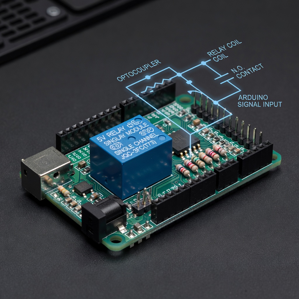
What is a Relay?
A relay is an electrically operated switch. It allows a low-voltage circuit (Arduino) to control a high-voltage circuit (like 120V AC lights).
Why Use a Relay?
- Arduino outputs only 5V and 40mA
- Cannot directly control home electrical devices
- Relay acts as a bridge between Arduino and high voltage
Types of Relay Modules
| Channels | Description |
|---|---|
| 1 Channel | Controls 1 device |
| 2 Channel | Controls 2 devices |
| 4 Channel | Controls 4 devices |
| 8 Channel | Controls 8 devices |
Relay Module Specifications
Common 1-Channel 5V Relay
| Parameter | Value |
|---|---|
| Operating Voltage | 5V |
| Coil Current | 70mA |
| Contact Rating | 10A 250VAC |
| Trigger Level | LOW level trigger |
Pin Configuration
| Pin | Description |
|---|---|
| VCC | 5V from Arduino |
| GND | Ground from Arduino |
| IN | Signal pin from Arduino |
| NO | Normally Open contact |
| NC | Normally Closed contact |
| COM | Common terminal |
Connecting the Relay Module
Basic Connection
Arduino          Relay Module
5V       ------  VCC
GND      ------  GND
Pin 7    ------  INLoad (230V bulb):
L (Live)  ---[Bulb]---  COM
                       |
                      NO (when triggered)

N (Neutral) ----------------------
Circuit Diagram
Low Voltage Side (Arduino)     High Voltage Side (230V)
+------------------+          +------------------+
|                  |          |                  |
|   Arduino        |          |   Mains Power    |
|   Pin 7 ---------+---IN    |                  |
|   5V   ---------+---VCC    |   Bulb/Lamp      |
|   GND  ---------+---GND    |        |         |
+------------------+          |        +--COM    |
                              |        |         |
                              |   NO---+         |
                              |                  |
                              +------------------+
Basic Code
Turning Load On/Off
const int relayPin = 7;void setup() {
pinMode(relayPin, OUTPUT);
}
void loop() {
digitalWrite(relayPin, HIGH); // Turn on (NO closes)
delay(3000); // Wait 3 seconds
digitalWrite(relayPin, LOW); // Turn off (NO opens)
delay(3000); // Wait 3 seconds
}
With Button Control
const int relayPin = 7;
const int buttonPin = 2;void setup() {
pinMode(relayPin, OUTPUT);
pinMode(buttonPin, INPUT_PULLUP);
}
void loop() {
if (digitalRead(buttonPin) == LOW) {
digitalWrite(relayPin, HIGH); // Turn on
} else {
digitalWrite(relayPin, LOW); // Turn off
}
}
Project: Temperature-Controlled Fan
Control a fan based on temperature:
const int relayPin = 7;
const int tempPin = A0;
const int fanOnTemp = 30; // Celsiusvoid setup() {
pinMode(relayPin, OUTPUT);
pinMode(tempPin, INPUT);
}
void loop() {
int reading = analogRead(tempPin);
float voltage = reading * 5.0 / 1024.0;
float tempC = (voltage - 0.5) * 100;
if (tempC > fanOnTemp) {
digitalWrite(relayPin, HIGH); // Turn on fan
} else {
digitalWrite(relayPin, LOW); // Turn off fan
}
delay(1000);
}
Project: Automatic Night Light
Turn on light when it gets dark:
const int relayPin = 7;
const int ldrPin = A0;
const int darkThreshold = 300;void setup() {
pinMode(relayPin, OUTPUT);
pinMode(ldrPin, INPUT);
}
void loop() {
int lightLevel = analogRead(ldrPin);
if (lightLevel < darkThreshold) {
digitalWrite(relayPin, HIGH); // Night - light on
} else {
digitalWrite(relayPin, LOW); // Day - light off
}
delay(500);
}
Safety Warnings
⚠️ IMPORTANT: High Voltage Danger
Working with mains voltage (120V/230V) can be lethal!
Safety Rules
1. Always disconnect power before wiring 2. Use proper insulation on all connections 3. Never touch bare wires when powered 4. Keep the circuit isolated from Arduino 5. Use proper enclosures for final projects
Recommended Practices
- Use proper electrical box for high-voltage parts
- Label your circuit clearly
- Test with low-voltage load first (like 12V)
- Have someone experienced supervise
- Consider using optocouplers for extra isolation
Multiple Relays
Controlling multiple devices:
const int relay1 = 7;
const int relay2 = 6;
const int relay3 = 5;
const int relay4 = 4;void setup() {
pinMode(relay1, OUTPUT);
pinMode(relay2, OUTPUT);
pinMode(relay3, OUTPUT);
pinMode(relay4, OUTPUT);
}
void loop() {
// Turn on sequentially
digitalWrite(relay1, HIGH);
delay(500);
digitalWrite(relay2, HIGH);
delay(500);
digitalWrite(relay3, HIGH);
delay(500);
digitalWrite(relay4, HIGH);
delay(2000);
// Turn off all
digitalWrite(relay1, LOW);
digitalWrite(relay2, LOW);
digitalWrite(relay3, LOW);
digitalWrite(relay4, LOW);
delay(2000);
}
Summary
Relay modules bridge Arduino and high-voltage devices:
- Low-level trigger activates with LOW signal
- NO (Normally Open) closes when activated
- NC (Normally Closed) opens when activated
- Always prioritize safety with high voltage
- Can control lights, fans, motors, appliances
Next Lesson
In the final lesson, you'll complete a project combining everything you've learned.
Quiz - Quiz - Relay Module
1. What is the main purpose of a relay?
2. What does NO stand for on a relay?
3. What happens when a LOW level trigger relay is activated?
4. What is a safety consideration when working with relays?