Reading Schematics
Reading Schematics
What is a Schematic?
A schematic (circuit diagram) shows how components are connected using standardized symbols.
Visual Example
Here's what a schematic diagram looks like:
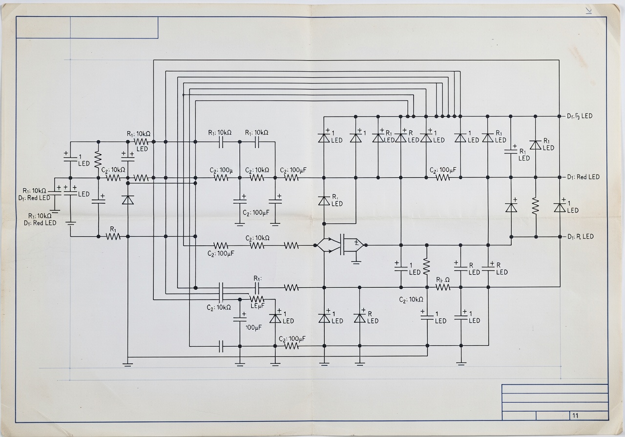 Electronic circuit schematic - the universal language of electronics
Common Symbols
Power
- VCC, +V: Positive supply
- GND, Ground: Negative/return
- Battery: Parallel lines (long = +)
Passive Components
- Resistor: Zigzag (US) or Rectangle (IEC)
- Capacitor: Two parallel lines
- Inductor: Looped wire
Semiconductors
- Diode: Triangle + line
- LED: Diode + arrows
- Transistor: Various symbols
Other
- Switch: SPST, SPDT
- Fuse: S-shaped line
- Speaker: Box with cone
Schematic Conventions
Reading Direction
- Signal flows left to right
- Power flows top to bottom
Net Names
- Same net names = connected
- Lines without connections = separate
Values
- Values written on components
- Units: Ω, kΩ, MΩ, μF, pF
Example: LED Circuit
+Vcc (9V)
  |
  ├──[R1]──[LED]──GND
This shows:
- 9V supply
- Resistor R1 connected to LED
- LED connected to ground
Finding Components
1. Identify power (VCC, GND) 2. Find inputs/outputs 3. Follow signal path 4. Identify components
Tips for Beginners
- Start with simple circuits
- Label each component
- Trace one path at a time
- Use multimeter to verify
Summary
- Schematics use standardized symbols
- Power typically at top
- Signal flows left to right
- Practice with simple circuits
Congratulations!
You've completed the Electronics Fundamentals course! Keep experimenting and building.
Quiz - Quiz - Reading Schematics
1. What do VCC or +V symbols represent?
2. In which direction does signal typically flow in schematics?
3. What does a zigzag line represent in a US schematic?