Series and Parallel Connections
Series and Parallel Connections
Visual Comparison
Let's start with a visual understanding of the difference:
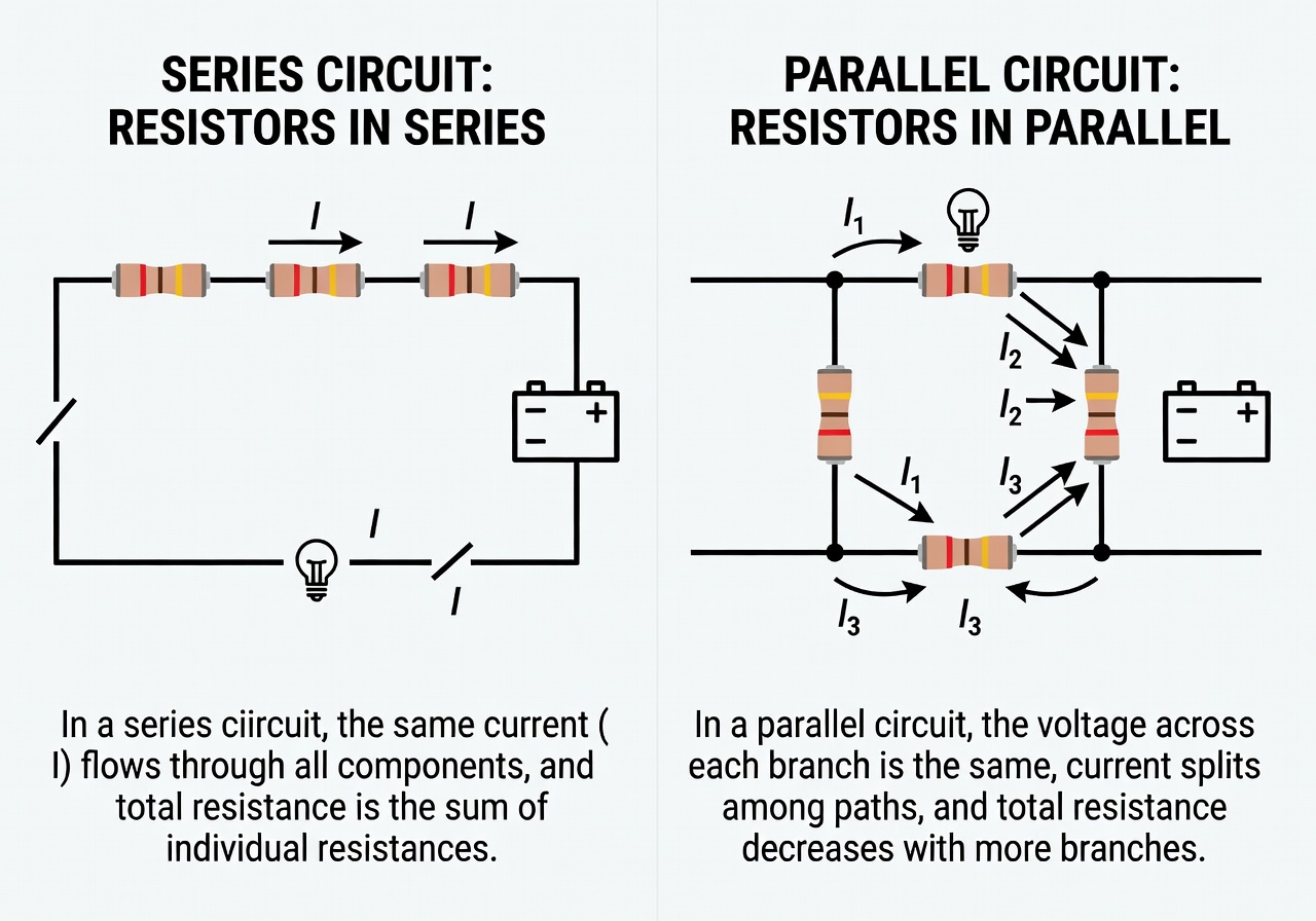 Series circuit (left) has one path for current, parallel circuit (right) has multiple branches
Series Circuit
Components connected one after another in a single path.
Characteristics
- Same current flows through all components
- Total resistance = sum of all resistances
- Total voltage = sum of voltage drops
Example
R1 (10Ω) + R2 (20Ω) = 30Ω total
Uses
- Current limiting
- Voltage dividing
Parallel Circuit
Components connected across the same two points.
Characteristics
- Same voltage across all components
- Total current = sum of branch currents
- Total resistance decreases
Example
1/Rtotal = 1/R1 + 1/R2
1/Rtotal = 1/10 + 1/20
Rtotal = 6.67Ω
Uses
- Multiple power outlets
- Redundancy
Series vs Parallel
| Property | Series | Parallel |
|---|---|---|
| Current | Same | Splits |
| Voltage | Splits | Same |
| Total R | R1 + R2 | 1/(1/R1 + 1/R2) |
| If one breaks | Circuit opens | Other keeps working |
Mixed Circuits
Most real circuits combine both:
Battery → Resistor → LEDs (parallel) → Switch → Battery
Summary
- Series: Current same, voltages add, R adds
- Parallel: Voltage same, currents add, R decreases
- Real circuits are usually combinations
Next Lesson
In the next lesson, you'll build your first circuit - an LED with a battery.
Quiz - Quiz - Series and Parallel Connections
1. In a series circuit, what is the same across all components?
2. In a parallel circuit, what is the same across all branches?
3. Two 10Ω resistors in parallel give what total resistance?